The keys to properly using a dial indicator are precision and patience. The payoff is a long-lasting driveline. The dial indicator is one of those specialized tools that has an intimidating reputation, but as with many things, understanding the components of the tool and how they work is half the game. A dial indicator typically measures the backlash of a ring and pinion gear. It can also be used to measure runout, the untrue movement (wobble) of a rotating object like an axle, cam or crankshaft journal, wheel, brake rotor, or the input shaft of a manual transaxle/transmission. Precision is important because in ring and pinion jobs we are dealing with shims that can be paper sheet thin… as thin as three thousandths of an inch. The first step to dial indicator enlightnement is understanding the workings of the tool.
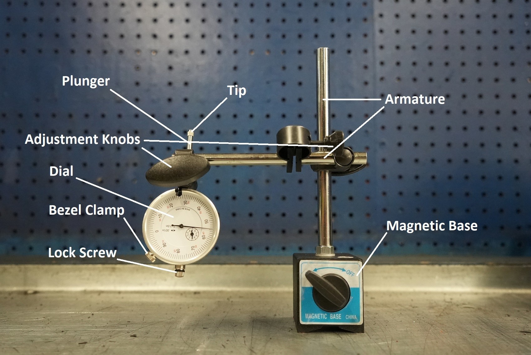
Anatomy Of A Dial Indicator
When measuring backlash in a ring gear the placement of the dial indicator is key. High-pinion and low-pinion applications have the drive side gear teeth on different sides of the ring gear. This will determine where the dial indicator is set up because measurements are made on the drive side of the tooth.
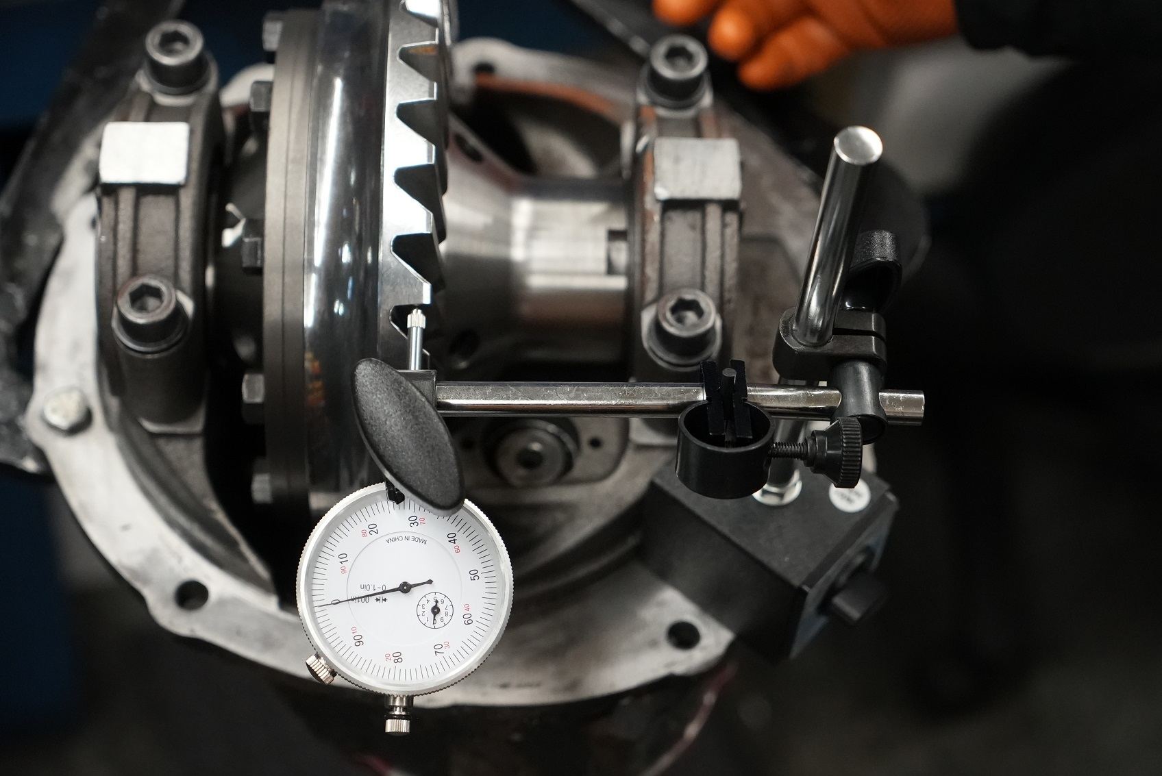
The Setup
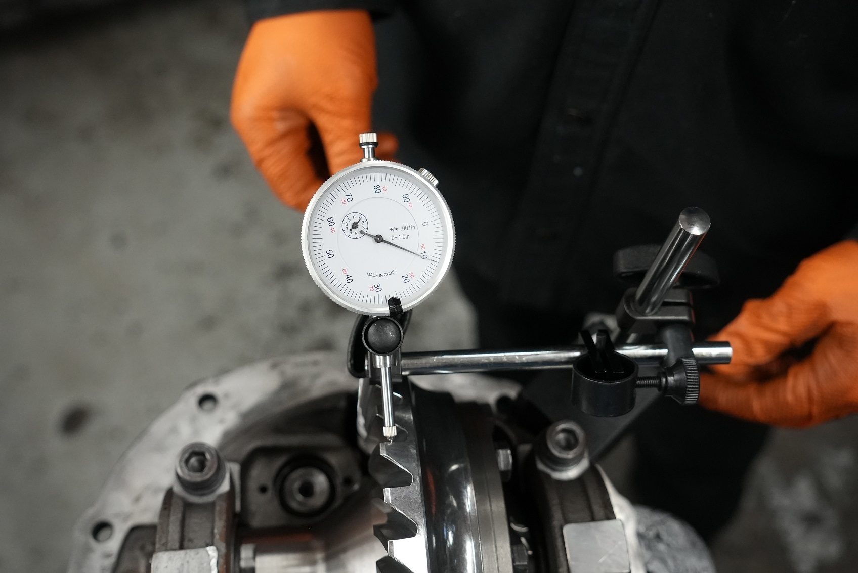
A dial indicator is like a high-tech erector set. It can be extended and articulated in an array of angles. Setting up the unit starts with the magnetic base which is placed on the housing and then all the armature is configured to position the tip at a 90-degree angle on the drive gear tooth with the plunger in proper alignment with the gear’s rotation 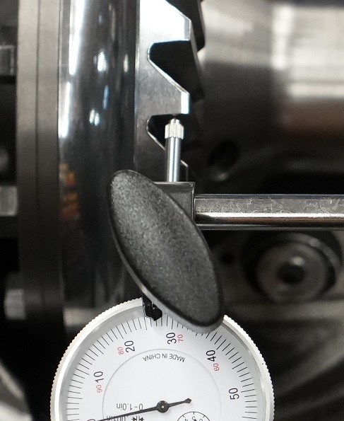 angle.
A vast majority of dial indicators have magnets that you position to aling the plunger and ring gear tooth. In whatever manner the base of your dial indicator secures to the housing, it must maintain a stable platform because every proceeding step relies on the accuracy and consistency of this starting point. Here, the diff housing makes a great anchor point but other applications may not offer so obvious mounting possibilities.
The arm can be moved up or down the main shaft while also being adjusted inward and outward within the housing to more precisely line up the tip and the tooth face. This is where your erector set experience comes into play.
There is an adjustment knob behind the dial that allows the dial assembly and plunger to swivel to better match the actuation of the tip with the angle of the gear tooth when the ring gear is moved. The goal is to make as much of a straight line measurement as you can. Tighten everything down to limit flex and be sure the tip is resting on the tooth face… any play or preload in this area will produce false readings. Also, be sure the plunger is not rubbing against the adjacent tooth which may also result in a faulty measurement.
Shop Yukon dial indicators and measuring tools here.
Measuring
You can measure with the existing readout or zero-out the tool by loosening the bezel clamp and rotating the bezel. When measuring backlash on a ring gear be sure you’re only turning the gear and not the pinion which may influence the readout. Clamping or otherwise isolating the pinion is a good idea. When measuring a ring gear, the gear is rotated in both directions to produce freeplay. The amount of the movement is measured as straight-line travel by the tip and plunger. Even the runout of a ring gear can be evaluated by measuring the amount of movement the gear produces back and forth between the thrust bushings.
Reading The Dial
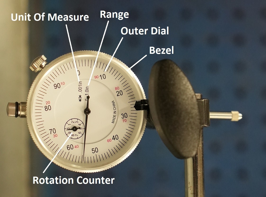
Most dial indicators have a one-inch stroke, meaning the plunger will only move one inch within the tool. The dial indicator’s range is denoted in the dial. The dial also has units of measure or accuracy indicated, typically in drivetrain operations a 1/1000 of an inch is the preferred unit. The main or outer dial is joined by the smaller revolution counter dial which indicates how many times the needle has gone around the outer dial. So, if the main needle travels around the outer dial twice the revolution dial will read 2. Or 0.200 inches. If the larger needle progresses past zero to 30 on the big dial, the total reading is 0.230 or 230 thousandths of an inch.
Total Movement
The amount of positive movement and negative movement indicated reveals the total movement. So, the measurement is made from the static beginning with the plunger engaged then it moves inward and outward and the number of units measured in each direction are added together.
For instance, if the needle moves from plus five thousandths of an inch to minus 90 thousandths of an inch, the total needle movement is 15 thousandths of an inch. Additionally, if the needle moves 10 thousandths of an inch to the negative side and then five thousandths of an inch to the positive side the total movement is again 15 thousandths of an inch.
Once you successfully set up the dial indicator measuring other gear sets will be super easy as long as they have the same pinion arrangement i.e. high pinion or low pinion, as the basic setup of the tool’s armature has been established and you’ll only need to fine tune the tip-to-tooth relationship.
Dial indicators deserve a place of honor in your tool case. They expand our capacity, allowing us to do more jobs. They add quality to our work, by enhancing the accuracy of our actions. The end result is a job better done that will last for years to come, a win-win in anyone’s book.
 AMC
AMC
 Chrysler
 Dana
Dana
 Ford
Ford
 GM
GM
 Isuzu
Isuzu
 Nissan
 Suzuki
 Toyota
